Introduced: 1986
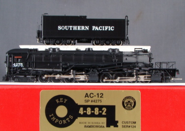
These Key SP 4-8-8-2 cab-forwards have a somewhat complicated history. Key imported their first 4-8-8-2 (an AC-12) in 1984. And unlike these models, it was manufactured in Japan by Nakamura. All subsequent versions were manufactured in Korea by Samhongsa. The Nakamura AC-12 is covered elsewhere in this encyclopedia, but I will note here that the Nakamura AC-12 is much more highly regarded (both in terms of detailing and performance) than any of these Samhongsa models. It also tends to sell for several hundred dollars more than any of these models.
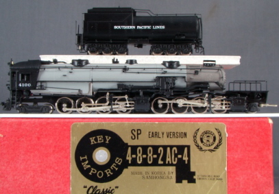
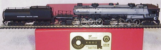
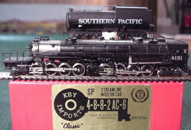
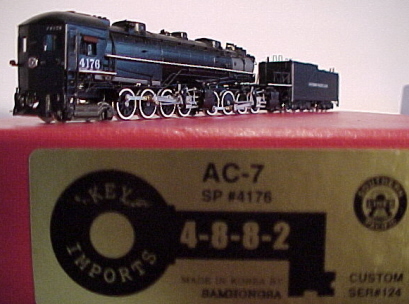
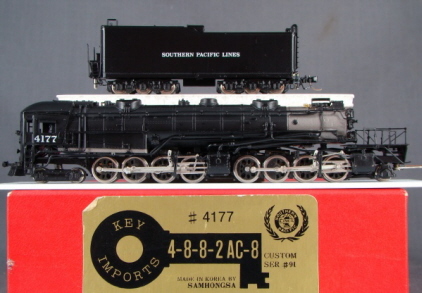
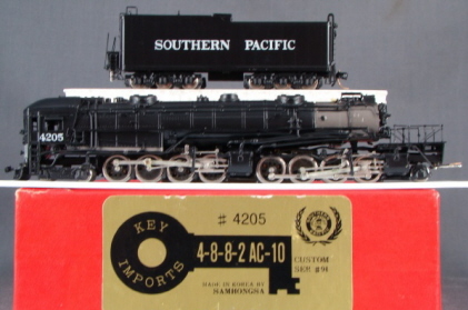
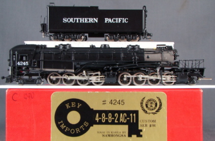
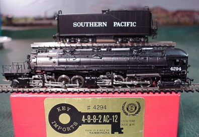
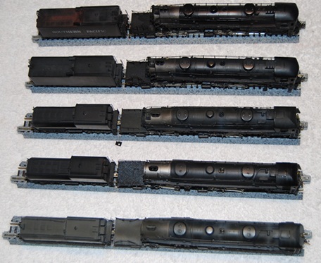
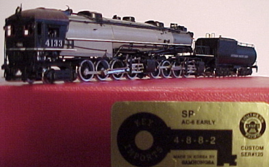
Samhongsa's Cab-Forwards came out in dribs and drabs over the course of the 80s and 90s. The first release (AC-4, AC-5, AC-6) came out in 1986 and did not have a SER # on the label. The second release (AC-7, AC-8, AC-10, AC-11, AC-12) came out in 1990 with SER #91. The third release (AC-4, AC-5, and AC-6) came out in 1997 with SER #120. The fourth release (AC-7, AC-8, AC-10, AC-11, AC-12) came out in 1999 with SER #124.
I don't know every single difference between the various production runs, but here's what I do know - the first run has leaf springs for the driver suspension, whereas all subsequent releases have coil springs. SER #120 and #124 have a running plate between the engine and tender (which can be flipped up and down). Previous runs do not have this feature. SER #120 and #124 also have a differently configured driveshaft (two cups with a small universal shaft between them vs a ball-and-cup connection). SER #124 has a coreless motor (previous runs have various Sagami can motors). SER #124 also has better detailing (numbers on the cab number boards, a cab window shield, blackened wheels, etc).
As for the differences between the actual prototypes (AC-X vs AC-Y), here's a brief (and muchly boiled down) history of the Southern Pacific 4-8-8-2 -
- AC-4 - SP's first cab forward locomotive
- AC-5 - Slightly larger than the AC-4
- AC-6 - Slightly larger than the AC-5, and with a higher boiler pressure and tractive effort rating. With this release, most of the
SP's cab-forwards were re-equipped with larger cab windows (said redesign becoming the standard beginning with the AC-8)
- AC-7 - Slightly larger than the AC-6, equipped with a larger tender, and coming with a beveled cab front (in contrast to the earlier
flat cab front)
- AC-8 - Slightly larger than the AC-7, and the first to receive larger cab windows as standard equipment
- AC-10 - The largest class of cab forward steam locomotives produced for the railroad
- AC-11 - Built between November 1942 and April 1943, these closely resembling the AC-10s
- AC-12 - The last class of steam locomotives ordered by Southern Pacific, and once again, closely resembling the AC-10
Each respective AC-X model reflects the prototypical differences of its class (including prototypical details specific to the road number in question).
Not surprisingly, the mechanism is an extremely complex affair. The engine chassis is all metal and fairly minimalistic (with most of the actual heft being provided by the shell).
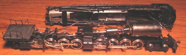
As noted above, the motor in the first three releases is a closed-sided Sagami "can" (and presumably a 3-poler). Ser #124 (not pictured) has a coreless motor. Right-rail pickup is provided by the eight right-side drivers. Left-rail pickup is provided by the six left-side tender wheels. The rest of the drivers, along with the pilot and trailing trucks are electrically neutral. Current is transferred from the tender to the engine by way of a stiff wire on the locomotive drawbar (and from said drawbar to the motor by way of a really long wire). Driver current flows into the engine shell and is then routed to the motor by yet another wire. Said wire is a bit annoying as it prevents one from completely disconnecting the mechanism from the shell.
The driveshaft design is a bit unusual, what with it extending at a downward angle from the motor to the forward engine's worm gear, and then continuing on (also downward) to the rear engine. Said driveshaft consists of a complex assembly of metal and plastic bits and pieces. Only one axle per engine is geared (with all the rest of the drivers being turned solely by the valve gear). The left-side (IE, electrically neutral) geared drivers are equipped with traction tires. All gearing is metal. The worm gears live inside little housings that are spring-cushioned (which I assume is a good thing, although I couldn't really tell you why). Each axle is held in place by bearing blocks, and each bearing block has a tiny spring between it and the chassis (both providing downward pressure as well as a bit of up-and-down flexibility).
A fixed (IE, non-operational) coupler is mounted to the pilot. There is no coupler on the tender (although a Micro-Trains friendly pocket is provided). The locomotive has a working (albeit non-directional) headlight. The tender has a fake (IE, non-operational) back-up light assembly built into it.
There's no question that these are beautiful models of a very cool prototype (and with working headlights, no less). However, it's been my experience that most of them don't run particularly well out of the box (and some of them barely run at all). The main problem is getting current to flow reliably from the tender to the engine, and that stiff drawbar wire is the primary weak link. As delivered, it's generally loose and floppy and, as a consequence, unable to stay in firm contact with the tender peg. The end result is a lot of stuttering and stalling. The easy solution is to glob a bit of solder on the wire where it connects to the drawbar. This will serve to stiffen it up and allow it to make firmer and more reliable contact with the tender peg. A more ambitious solution would be to run an insulated mini-wire from the tender to the locomotive.
Another problem with the tender is that it's just too darned light. Even after making the drawbar mod, my 4-8-8-2 still couldn't make it through a curve without stalling. And after a lot of frustrating experimentation, I eventually decided to try popping open the tender and sticking in a half ounce worth of lead weight. And lo, this actually went a long way towards improving performance. Now I can basically get it to navigate a circle of track pretty smoothly at about 3/4 throttle. But really, that's about it. Slow speed performance is marginal at best, and often changes radically depending on how lucky you got when you hooked the tender to the drawbar. Sometimes the current flows seemlessly and other times, ugh, not so much.
My other gripe with these models is the valve gear. I don't know if it's the design or the implementation (or both), but it all seems just a bit bindy. Consequently, it takes a lot of throttle to get these things moving. And once they do finally decide to get moving, they tend to lurch forward like a sprinter. Now, experienced steam tinkerers may be able to make the necessary adjustments to achieve smoother performance. But if you're like me, messing around with all the various rods and cranks on a complicated steamer usually winds up making things worse rather than better. I suppose one could always hope that things will smooth out after some running in, but I wouldn't bet the mortgage on it.
As one might expect, these models are completely useless on narrow radius curves. Anything sharper than about 19"-radius is going to cause the loco to derail (and even 19" is pushing it). On the plus side, the wheels are low-profile, so no problems on Code-55 rails.
So, I guess there is some potential here if you're an experienced tinkerer / tuner (or if you happen to luck out and get one that was put together correctly). They appear to be at least capable of running smoothly and quietly. But if you're expecting to take one out of its box, put it on the rails and run it, you're probably going to be severely disappointed.
I'm told that these were produced in relatively limited numbers (perhaps as few as 15-25 per road number). Which goes a long way towards explaining why they rarely show up on eBay.
Taking these things apart is a bit arduous (and getting them put back together is even more fun). To remove the rear engine, first unscrew the bar that connects it to the forward engine. Next, find the sliding steam line at the back of the engine. It slides forwards and backwards in a little slot in the boiler shell. Slide it forward until it pops out of the hole provided at the end of the slot. The forward engine is held to the boiler shell with two small screws. The first is up by the pilot coupler and the second can be found underneath the aforementioned bar that connects the two engines together (you won't be able to see said screw until said bar has been moved out of the way). The forward engine is tangled up underneath a bunch of steam piping, so it takes a bit of finagling to get it out of there. As mentioned previously, a wire runs from the motor into the shell, so you won't be able to completely separate the forward engine (not without first yoinking that wire, anyway). Note that the forward driveshaft connects to the rear driveshaft with a short plastic connector piece. One end is keyed and slides into a hole on the forward driveshaft. The other end is pronged and clips to a plastic connector on the rear driveshaft. And believe me, getting that damned thing reconnected is a freaking nightmare. Sadly, there really isn't any way to adequately lubricate the gears without basically dismantling the entire locomotive first. Have fun!
Grade: D (as delivered)
(Thanks for the pictures, Chris)