
USRA 2-6-6-2
Introduced: circa 1994
These models all came out around the same time and share the same basic internals. So, to save myself some time (not to mention money), I'm going to cover them all here based on the one guinae pig that I've actually purchased and tested (a C&O H-5 2-6-6-2). Based on the pictures above, I can't really tell what external differences there might be between the various 2-6-6-2 models. But given the different prototyical designations (USRA, I-3, and H-5) I'm assuming they boil down to minor differences in shell detailing. Note that some (or perhaps all) of the USRA 2-6-6-2's came painted/unlettered (with a sheet of decals included in the box). These are all extremely fine lookings models (as one would expect from brass). As for the performance? Well, not so good (but more on that in a moment).
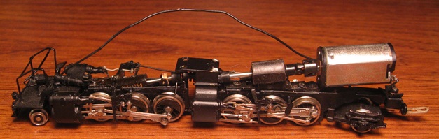
As generally seems to be the case with articulated steamers, the mechanism is a complex one. The "chassis" consists of two flimsy metal skeletons, connected together by a center drawbar. The motor is a closed-sided can (with no indications as to its origins). And being closed-sided, I can only guess as to its internal characteristics (but most likely three-pole and straight-wound). Right-rail pickup comes from five of the six right-side drivers and left-rail pickup comes from the left-side tender wheels (with current transferred to the locomotive by way of a stiff wire on the tender drawbar). All the rest of the wheels are electrically neutral.
The rearmost pair of drivers is equipped with traction tires (a non-TT driver set is included in with the spare parts should you wish to exchange more pickup for less pulling power). The motor driveshaft turns a worm in a spung worm tower on the rear engine. A secondary driveshaft (with a pair of plastic connectors) connects the rear worm tower to the forward worm tower (also sprung). Only one axle per engine is geared and all gearing is brass. All six driver axles are held to the chassis by brass bushings (aka bearing blocks). A lengthy wire transfers left-rail current from the motor to a non-directional headlight mounted on the pilot assembly. There is no tender lighting. A fixed (non-operational) knuckle coupler is mounted to the pilot. There is no coupler on the tender, although a pre-drilled hole is provided for mounting a Micro-Trains coupler. Wheels are low-profile, so no problems on Code-55 rails.
The only thing holding the forward engine to the boiler shell is an articulated steam pipe (which rides in a slot on the shell). And given the mounting (or, should I say, lack of mounting), the boiler shell winds up sitting at kind of a funny angle (with the cab end riding a bit lower to the rails than the front end). Kind of weird looking, if you ask me.
As always seem to be the case with steam locomotives that use that "stiff wire on the drawbar" scheme to transfer current from the tender to the engine, performance is kind of a mixed bag. The mechanism itself is well designed and runs smoothly and quietly when current is constant. Unfortunately, given the "luck of the draw" nature of the tender connection, current transfer is all over the map. Sometimes you get a solid connection and other times you don't (and in the latter case, the end result is a lot of stuttering and even out-and-out stalling). I'm not real impressed with the motor either, as the starting speed is a bit high (and, not surprisingly, the top-end speed is really high). On the plus side, I didn't have any problems with any of the wheels derailing. Given the heavy brass shell and traction-tires, pulling power is strong. As far as curves go, the 2-6-6-2's can handle extremely sharp ones (right down to 9.75" radius). Conversely, the 2-6-6-6 is limited to curves no sharper than about 14"-radius (owing to the larger trailing and tender trucks).
A relatively simple solution to the drawbar conductivity issue would be to replace the single stiff wire with a pair of stiff wires (or more accurately, a single wire bent into a "U"). Samhongsa actually adopted a scheme very much like this for some of their later steamers (y'know, the ones that actually run good) -
Another solution would be to simply run an insulated mini-wire from the tender to the motor. But anyway, ultimately what we have here are some very nice looking brass steamers that, unfortunately, don't really cut it in the performance department (not as delivered, anyway).
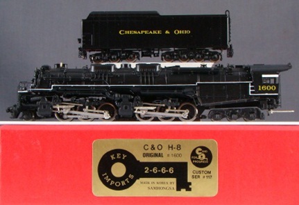
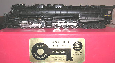
In addition to the "Original" version (pictured above), the 2-6-6-6 was also available in "Middle" and "Late" versions -
To remove the locomotive shell, first remove the two small screws on the back of the cab. Next, remove the screw holding the center drawbar to the forward engine (said screw has virtually no slot on it, so be careful). Slide the forward engine backwards until the articulated steam pipe pops out of its slot in the boiler shell. The forward engine should now lift up and off, revealing the two small screws that hold the rear engine to the chassis. Remove these and the rear engine should lift up and out as well. And wow, look, your driveshaft has now fallen apart. Hurray! As for getting everything put back together? Wow, good luck with all that... Basically you need to get the engines reattached to the chassis and then spend the next several hours getting the driveshaft between the two engines reconnected. Once that's been accomplished, reattach the center drawbar and you're ready to roll.
Grade: C